Emech 4 Bar linkage Tutorial
*
Emech 4 Bar linkage Tutorial *
4-Bar Linkage Motion Study
After building the four-bar linkage in SolidWorks, I used Motion Study to see how the mechanism behaves during a full rotation of the crank. A rotary motor was applied to the crank so the linkage would continuously rotate while I recorded velocity and torque data during the motion.
To understand how the coupler moves, I tracked the velocity of the midpoint of the link in both the X and Y directions. The plots show that the velocity is not constant. As the crank rotates, the geometry of the linkage changes, which causes the midpoint to speed up and slow down throughout the cycle. The X and Y velocity plots together show that the coupler follows a curved path rather than simple straight-line motion.
I also measured the torque required to drive the mechanism. The torque is not constant and changes depending on the configuration of the linkage. The maximum motor torque from the simulation is about 17 N·mm, which occurs near the beginning of each rotation cycle when the linkage is in a less efficient position.
Using the crank radius of 0.07 m and rocker radius of 0.120 m, I estimated the forces at to be approximately 242.85 N and 141.67 N. Based on the torque results, the motor power required to run the system at 600 rpm is about 0.44 kW.
One interesting result is that the torque becomes negative at certain points in the cycle. This means the mechanism is helping drive the motion at those points instead of resisting it.
Overall, the motion study helped show how the geometry of the linkage affects velocity, torque, and the loads in the system.
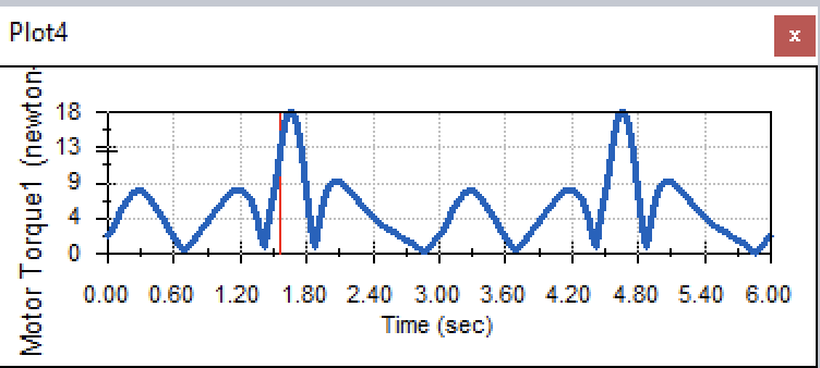
Motor Torque Graph