4 Bar Linkage
Summary:
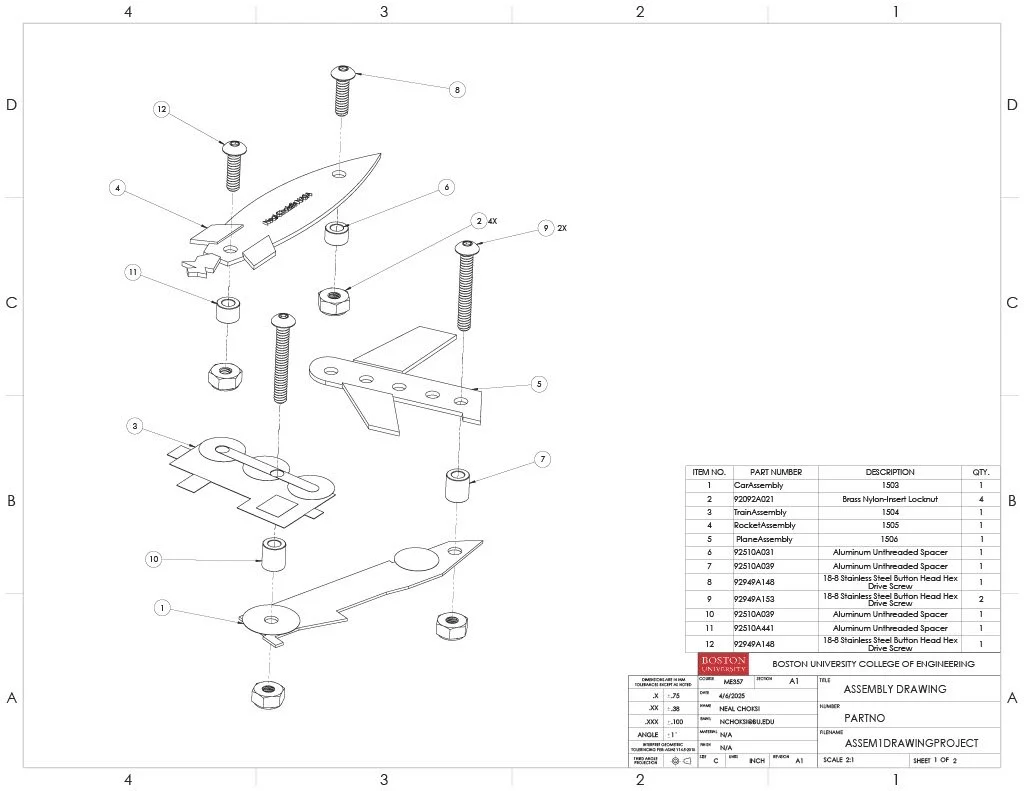
This four-bar linkage project helped me understand how mechanical motion can be analyzed, visualized, and verified using CAD tools rather than just theoretical equations. Modeling the linkage required careful attention to link lengths, pivot locations, and constraints to ensure the mechanism moved smoothly without interference or over-constraint.
Creating the assembly and defining the correct mates taught me how small errors in joint placement or alignment can dramatically change the motion of a mechanism. Adjusting the geometry and re-testing the motion reinforced the importance of precision when designing kinematic systems, especially those with multiple rotating links.
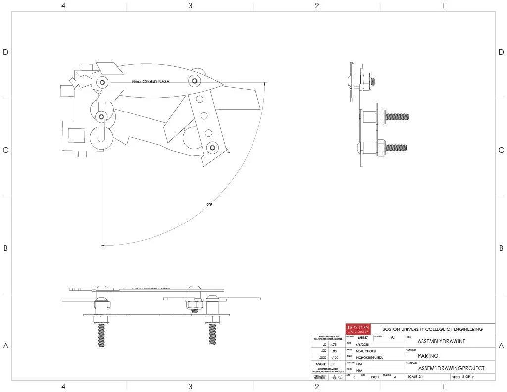
A key part of this project was plotting points on the linkage over time to generate motion graphs. By tracking specific points in SolidWorks and exporting their positions, I learned how to translate mechanical motion into quantitative data. This process helped bridge the gap between visual motion and analytical understanding, allowing me to evaluate displacement paths, trends, and repeatability throughout the motion cycle.
Analyzing the plotted data made it clear how design choices affect motion behavior. Changes to link lengths or pivot locations produced noticeable differences in the trajectory of tracked points, which reinforced the sensitivity of linkage systems to geometry. This helped me better understand how engineers validate mechanisms before physical prototyping.
Overall, this project strengthened my understanding of kinematics, mechanism design, and motion analysis. It taught me how CAD tools can be used not just for modeling parts, but for studying system behavior, verifying design intent, and supporting engineering decisions with data.